The Secret of Efficient and Stable LED Driver Power Supplies: Key Considerations for MOSFET Selection
As the core component of LED lighting products, LED driver power supplies have strict requirements on the performance parameters of power devices. As a key switching component in LED driver power supplies, the performance of MOSFETs directly affects the energy efficiency, stability, and lifespan of LED lighting. Here, let's explore the relevant knowledge of LED driver power supplies.

Figure 1 Physical image of LED
I. Relevant Principles of LED Driving
-
Several Forms of Switching Regulator Circuits
LEDs are current-driven, and their brightness depends on the current. They are also voltage-sensitive devices; overvoltage can easily cause damage. Precise current drive control ensures stable LED operation and extends their lifespan. With the popularization of LEDs, the efficiency of their driver power supplies has also attracted much attention. A low-efficiency driver would result in a waste of electrical resources. Therefore, most current LED drivers are in the form of switching power supplies. In addition to stably outputting precise constant current and high power, their conversion efficiency of over 90% is an important reason for their widespread adoption. Figure 2 shows schematic diagrams of several common switching regulator circuits used in LED switching power supplies.
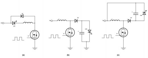


Figure 2 Switching regulator circuits
(a) Buck converter (b) Boost converter (c) Buck-Boost converter
Figure 2-(a) shows an LED driver circuit using a Buck converter. Unlike traditional Buck converters, the MOSFET switch VT is moved behind the inductor L, so that the source of VT is grounded, and the freewheeling diode VD is anti-parallel with the series circuit. This driver circuit is simple and does not require an output filter capacitor, reducing costs. However, the Buck converter is a step-down converter and is not suitable for occasions with low input voltage or multiple series-connected LEDs.
Figure 2-(b) shows an LED driver circuit using a Boost converter, which boosts the output voltage to a desired value higher than the input voltage through inductor energy storage, enabling LED driving under low input voltage.
Figure 2-(c) shows an LED driver circuit using a Buck-Boost converter. Similar to the Buck circuit, the source of VT in this circuit can be directly grounded. Although Boost and Buck-Boost converters have one more capacitor than the Buck converter, they can both increase the absolute value of the output voltage, so they are widely used in situations with low input voltage and the need to drive multiple LEDs.
Principles of LED Driver Topologies
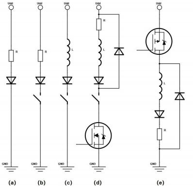
Figure 3 LED driver topologies
(a) Regulating LED current using a series resistor (b) Circuit controlling LEDs with programmable duty cycle (c) Circuit using low-side switch (switch mode method) (d) Implementation with freewheeling diode (e) Using high-side switch
(1) Regulating LED current using a series resistor (linear method) is the simplest way, as shown in Figure 3-(a). Its advantages include low cost, simple implementation, and no noise generated by switching. The main disadvantages of this topology are: power loss on the resistor reduces system efficiency; it cannot control LED brightness. Moreover, this scheme requires a regulated power supply to obtain a constant current. For example, assuming U is 5V and the LED's Uf is 3.0V, to generate a constant current of 350mA, the series resistor R is calculated as R = (U - Uf)/I, so R = (5 - 3.0)/0.35 = 5.7Ω. The power consumed by resistor R is RI², which is 0.7W (almost equivalent to the power of a white LED), so the overall efficiency is inevitably lower than 50%. In fact, the forward voltage VF of the LED changes with temperature, causing the current to change. Using a higher Udd can minimize the overall current variation caused by VF, but it will generate significant losses on the resistor, further reducing efficiency.
(2) Using a linear current source with a transistor and an operational amplifier, as shown in Figure 3-(b), can set the current very precisely to 350mA, but it still has the problems of low overall circuit efficiency and power loss in resistor R.
(3) The low-side switch (switch mode method) circuit, as shown in Figure 3-(c), can regulate the current flowing through the LED by allowing the current on inductor L to rise when the switch is turned on and fall when the switch is turned off. Like any inductive load, when the switch is turned off, a path for the current is needed. This can be achieved by the freewheeling diode in Figure 3-(d), where an N-channel MOSFET is used instead of the switch, and a resistor R is added to detect the current flowing through the LED. When the current drops to a low current threshold (e.g., 300mA), the switch turns on; when the current rises to a high brightness threshold (e.g., 400mA), the switch turns off. Turning on the FET only requires a 5V voltage at its gate, which can be directly provided by an output port of the microcontroller. Moreover, this topology no longer requires a constant Udd voltage and can stably regulate the LED current even if the input voltage fluctuates.
This topology is similar to the front end of a boost converter and has the advantage of using an N-channel, low-cost FET, but it requires a voltage differential measurement across resistor R to obtain the current flowing through the LED. The switch in the circuit actually provides two functions: first, it enables an adjustable current to be generated on the inductor; second, it allows adjustment of the LED brightness.
(4) Using a high-side switch. The difference between the high-side switch circuit and the low-side switch circuit is only the exchange of the load and the transistor. In the circuit shown in Figure 3-(e), the switch is located on the "high side", and the FET is changed from N-channel to P-channel. Because an N-channel FET requires Ugs > 5V, in the circuit shown in Figure 3-(e), the source voltage of the N-channel will constantly change, often above 3V, so at least 8V is needed at the gate.
This requires a gate drive circuit similar to a charge pump, making the entire circuit more complex. If a P-channel FET is used and -5V Ugs can be directly provided from the output of the microcontroller, the circuit is much simpler. This topology is similar to the front end of a buck converter. The main advantage of this circuit is that current detection can be performed directly across resistor R, so no differential detection method is needed.
-
LED Brightness Regulation Technology
In modern lighting systems, LED dimming technology is widely used to achieve brightness control. Although there are various dimming methods, most of them basically control the average brightness by quickly switching the LED on and off periodically. This method utilizes the human eye's insensitivity to high-frequency flicker, turning the LED on at rated current or off in a very short time to avoid visible flicker. The brightness of the LED is proportional to the proportion of time it is "on" (i.e., the duty cycle). MOSFETs are well-suited for this task of quickly switching LEDs due to their electrical characteristics.
There are two common LED dimming technologies:
-
Pulse Width Modulation (PWM)Pulse Width Modulation is one of the most commonly used LED dimming methods. It controls the brightness by setting a fixed period T and changing the length of the LED's on-time in each period. The longer the on-time, the higher the duty cycle, and the brighter the LED appears; conversely, it is dimmer.
As shown in Figure 4, by setting different duty cycles, such as 6%, 50%, and 94%, different brightness levels from dim to nearly full brightness can be achieved. This dimming method has fast response speed, high control accuracy, and does not change the color temperature of the LED, making it an efficient and stable dimming method.
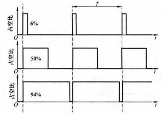
Figure 4 Pulse Width Modulation
Unlike PWM, frequency modulation uses control pulses of fixed width. In this method, the width of each control pulse remains unchanged, but its frequency is adjusted according to the required brightness.
As shown in Figure 5, the width of pulse A is always the same, and the brightness of the LED is achieved by controlling the repetition period of these pulses. The higher the frequency, the more times the LED is turned on per unit time, and the higher the brightness. Although this method has lower dimming accuracy than PWM, its circuit implementation is simple and has certain advantages in some low-power applications or applications with low dimming accuracy requirements.
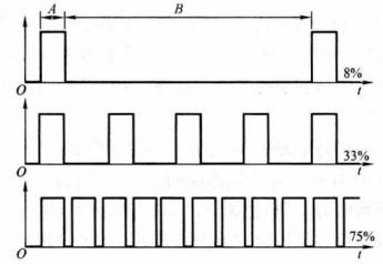
Figure 5 Frequency Modulation
In actual LED dimming circuits, the current is not completely free of fluctuations. In a good dimming circuit with soft or minimal strobing, the current fluctuation is small and imperceptible to the human eye. If the fluctuation is large, leading to severe strobing, it will cause great harm to the human eye in actual use. Figure 6 shows the relationship between the actual dimming signal and the LED current. It can be seen that the smaller and weaker the LED current fluctuation, the better the actual lighting effect, which is closely related to the LED driver switching devices.
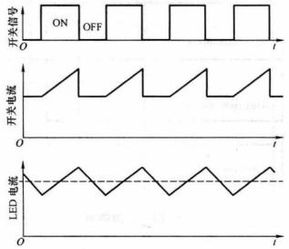
Figure 6 Schematic diagram of LED switching current
-
LED Driver Chips and Peripheral Circuits
Figure 7 shows two commonly used LED driver chips. LM3409 is a buck-controlled high-power LED driver, and LT3756 is an LED driver IC that supports three driving modes (buck, buck-boost, boost). LM3409 is paired with a PMOS transistor, and LT3756 is paired with an NMOS transistor. It can be seen that LED driver ICs and MOSFETs are commonly combined; of course, some low-power driver chips do not require an external MOSFET, as the built-in MOSFET is sufficient to meet their driving requirements.
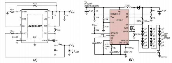
Figure 7 LED driver chips and peripheral circuits
II. Actual Display of LED Driver Power Supplies
LED power supplies are common electrical appliances, widely used in our office, home, and production environments. Figure 8 shows a common LED dimming board, which uses TM80N03 from Taimao Semiconductor.
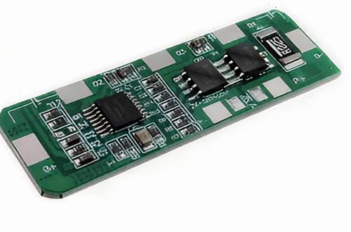
Figure 8 Display of LED dimming board (using TM80N03)
III. Precautions for MOSFET Selection in LED Driver Power Supply Circuits
With the above knowledge of LED driver power supplies and the display and analysis of actual products, we have a sufficient understanding of the role of MOSFETs in LED driver power supplies. Then, in actual projects, for different LED arrays, different LED driver chips, and different usage environments, how to select matching MOSFETs and what parameters should be paid attention to? The following is a list and summary:
-
Maximum drain-source voltage Vds
This is the maximum voltage that the MOSFET can withstand between the drain and source. A device with a Vds 1.5 to 2 times higher than the maximum operating voltage should be selected to retain sufficient margin and avoid damage from voltage spikes.
-
Maximum continuous drain current Id
It must meet the maximum current of the LED load, and consider transient currents such as startup and surge. A safety factor of 1.2 to 1.5 times should be reserved during selection to prevent the MOSFET from overheating or being damaged due to overcurrent.
-
On-resistance Rds(on)
The lower the on-resistance, the smaller the conduction loss and the higher the system efficiency. Especially in high-current or high-frequency working environments, low Rds(on) can significantly reduce heat loss.
-
Gate charge Qg
Gate charge Qg determines the switching speed and driving power consumption of the MOSFET. A smaller Qg means faster switching, which is suitable for high-frequency applications and helps improve efficiency. In addition, the MOSFET should match the operating frequency of the LED driver chip, and the heat dissipation capacity of the package and the assembly form should also be considered.
-
Input capacitance Ciss
Each time the MOSFET is turned on and off, it needs to charge and discharge the gate. The larger the input capacitance, the more charge is required for charging and discharging, and the slower the switching speed. The higher the switching frequency, the more switching times per unit time, and the more times the gate needs to charge and discharge.
Taimao Semiconductor offers more than 10 models for MOSFET applications in LED driver power supplies, covering the needs of most high-power LED driver power supply applications on the market, as shown in Figure 9.
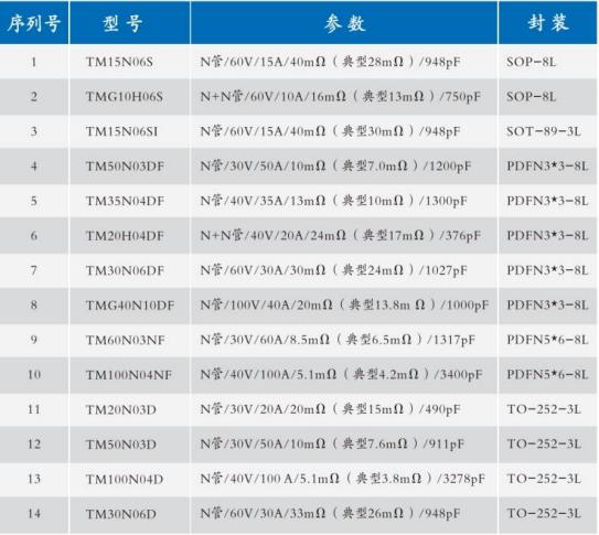
Figure 9 MOSFET selection matrix for LED power supplies
IV. Summary
LED driver power supplies may seem simple, but they are actually an exquisite combination of power control and semiconductor physics. Although MOSFETs are small, they bear the responsibility of efficiency, safety, and performance. A good selection is like adding brilliance to the light; a wrong selection may dim the light. Let us take technology as our wings and go further and shine brighter on the path of light.
